That said, I had a pretty un-memorable time working on the Bus' retrofit by way of Rocky Mountain Westy products. This isn't a dig at RMW, it's compliment! Most memorable experiences I have when wrenching are BAD memories. So 'unmemorable' is the highest compliment I can give.
Most of the RMW solutions are straight up bolt-on. During the week when I could work, I got a lot finished: and even more mocked up. Instead of just telling what I did, I decided the best use of this blog would be to show and comment, rather than describe to death. In this installment, we'll review the Rocky Mountain Westy Stainless Steel Exhaust system.
 |
| First installed are stand-offs that the heat-shield / muffler support mounts to. They replace the cam belt cover bolts. If you can't manage this part, you should probably not be working on your own car yourself. Also, you should probably get someone else to brush your teeth. (Tech Tip: Juice up the old cam cover bolts the night before with PB Blaster so you don't round off the bolt heads. Don't use an adjustable wrench or even an open end wrench: use a socket. This is not a component that you want to get stuck.) |
 |
| Heat shield mounted on standoffs. Note un-used vertical holes to the right (for muffler bracket and strap) and to the left (for EJ25 engines which have additional points which may accept standoffs.) One part that works for both engine applications. |
The standoffs hold the heat shield away from the plastic timing belt cover just enough to protect the cover and provide a finger-width distance from the crank pulley. It is a safe clearance, but replacing a belt would be cramped, and replacing the crank pulley itself would require dismantling the entire exhaust system. Still, that isn't a part that you're likely to replace on a whim. If you just MUST get your bling on with a new crank pulley, install it before you add the exhaust components.
Having bolted down the exhaust heat shield to the standoffs, I added the powder coated steel bracket for the 6" round Magnaflow muffler. Whenever possible, I flip the fasteners around so that the bolt head represent either the least ground clearance or hide the nuts and threads for aesthetic purposes. In this case, only the bolt heads are visible because they're facing to the rear where you look in at the engine: the threads and nuts are still accesible from above where you can't see them unless you climb into the engine compartment. Suffice it to say, the bracket hardware remains accessible while not flashing the less lovely bits to the public.
 |
| Powder coated 12ga. steel bracket bolted to .080 Corrugated Aluminum heat shield. This bracket is specifically designed to support the 6" diameter Magnaflow mufflers, though there is scarcely room in the cavity for anything else. The Subaru design expected to put the exhaust UNDER the engine, |
 |
| The T304 exhaust manifold for the right hand side exhaust port. RMW provides exhaust for both single and dual port EJ engines. |
The secret sauce for assembly is that the whole system is modular. Some folks have expressed nerves about slip-fit exhaust. If the whole thing were just held in place 'slip-fit' I'd agree. Instead, it uses Stainless Steel Torque-tite band clamps and the slip-fit joints are two inches deep (except for one, which I'll get to.)
The exhaust manifold prior to the CAT is a serpentine thing that each leg joins, then exits to the left, then swings back toward the right side via a 180° elbow to bend the exhaust flow up into the engine bay. The 180° elbow has a bung in it that the up-stream O2 sensor can be mounted in. In my case, I'm interested in the delta between the O2 values pre-CAT and post-CAT since my ECU has the capacity to measure both. (Recording the delta between the two lets you see what the efficiency of your CAT is and when it begins to fail. Some folks go without the upstream and just record the downstream values, tricking the ECU into thinking that the emissions are cleaner than they really are.)

(Note: Before you go cranking bolts down on the exhaust studs, make sure that you can get a properly fitting exhaust nut all the way up and down the stud; used studs are often pretty rusty or corroded. Running this simple exercise BEFORE you try to mount the manifold might make your life a lot easier just in the confidence of knowing that you can add new exhaust nuts to the existing studs and know that they'll come off again without snapping off the stud. Plenty of PB Blaster and some quality time running the new nut up and down the stud is worth a world of confidence when it comes to the final fit-up.)
Get the assembly under the car and bolt up to the exhaust ports, remembering to sandwich the gasket in between the manifold and the port. Tighten down your exhaust stud nuts to finger tight, such that the whole shebang wants to stay in place. Once both sides are done, wiggle until both sides are aligned, then add the torque-tite and tighten down on it until it wants to hang on. Torque-tite bolts are 14mm.
Run the same procedure for the 180° elbow. (It should still be able to pivot at both ends when finished, as you'll need to pivot around both the top and bottom portions of tubing and components as you rotate the assembly into final position.) This moves us to the top of the stack: The CAT and the muffler. Predictably, this is where it get interesting.
The muffler is the reversible Magnaflow 16450, a 6" round 18" long body with 3" long input / ouput pipes which are both offset from center on opposite sides. That CAT is also a Magnaflow unit.
 |
| This picture is a wealth of information: All of the slip-fit portions are dry fitted together and you can see some of the modifications that had to be made: 1) The left rear bumper bracket had to be clearanced, 2) The sequence of slip fit components means that each component added should have an input larger than the output. 3) the upstream O2 sensor visible behind the tubing elbow is screwed into place, 4) The muffler is BIG when lifted high into the space, necessitating the heat shield. All components are T304 Stainless Steel. |
First, we'll bob the inlet of the CAT, a Magnaflow 53034 recommended for this installation:

 |
| Take your muffler to a reputable muffler shop and have them stretch out either end (but not both) to accept the CAT's 2" OD outlet. Since one now fits inside the other, you just bought 25mm of width back. Best to take the CAT with you for a test fit. it should be as close a fit as you can manage. |
 |
| Here you can see the outlet of the CAT (left, with O2 sensor above) INSIDE the stretched inlet of the muffler (right). Fitting one inside the other buys back another 25mm, again shifting the muffler to the left. But now you must clamp these two together to make a seal: you can't 'unstretch' the muffler inlet pipe. Welding (since it is Stainless Steel) would be with TIG: Expensive. Instead, we'll make our own ersatz fitting. |
 |
Using the cutting wheel again on the inlet, cut 5 parallel relief cuts 20mm long equidistant
around the pipe, just short of where the pipe flares out to its largest diameter.
(If you pass that line where the pipe flares out, you'll never get it to seal. So don't botch it.)
|
Now you finally have the option of getting a clamp around this stinker and crimping down on it. As before, I used muffler cement liberally since this is the most likely spot (due to the relief cuts) for there to be leak. So I gooped up the inside of the muffler inlet and then inserted the outlet of the CAT all the way inside. Then I added the clamps shown below.
 |
| I used a basic set of 1-5/16in" to 2-1/4" dia adjustable Stainless Steel clamps sourced from my local Lowes. (PN 48536.) The mating area is thoroughly gooped up with muffler cement, and the clamps worked down tight. Between the friction fit, the clamping effect of the adjustable clamps and the pressure of tubing which can collapse and seal the better for the presence of the relief cuts, this should be a well sealed connection. |
So judicious trimming bought back enough space to be able to slip-fit all of the parts together and pull the right end in considerably. Total up all of the trims, and the muffler moved more than 1-1/2" to the left. But we're not quite through yet: We're going to shift the 180° elbow to the left, too, which will move the whole upper stack to the left by enough to allow the muffler to clear comfortably.
 |
| To shift the upper stack to the left, a compromise must be made at the bottom slipfit joint of the elbow. The elbow permits about a 2.25" overlap of the slipfit which is then covered by the 2" long Torqtite band clamp. To shift the whole upper stack to the left, I overlap the exhaust manifold by only 1.25" and then put the 2" bandclamp in place. |
 |
| The details of the trivial trim. No plasma cutter required, just an obnoxious swipe with a sharpie to follow, and some sacrificial cut-off wheels for my grinder. |
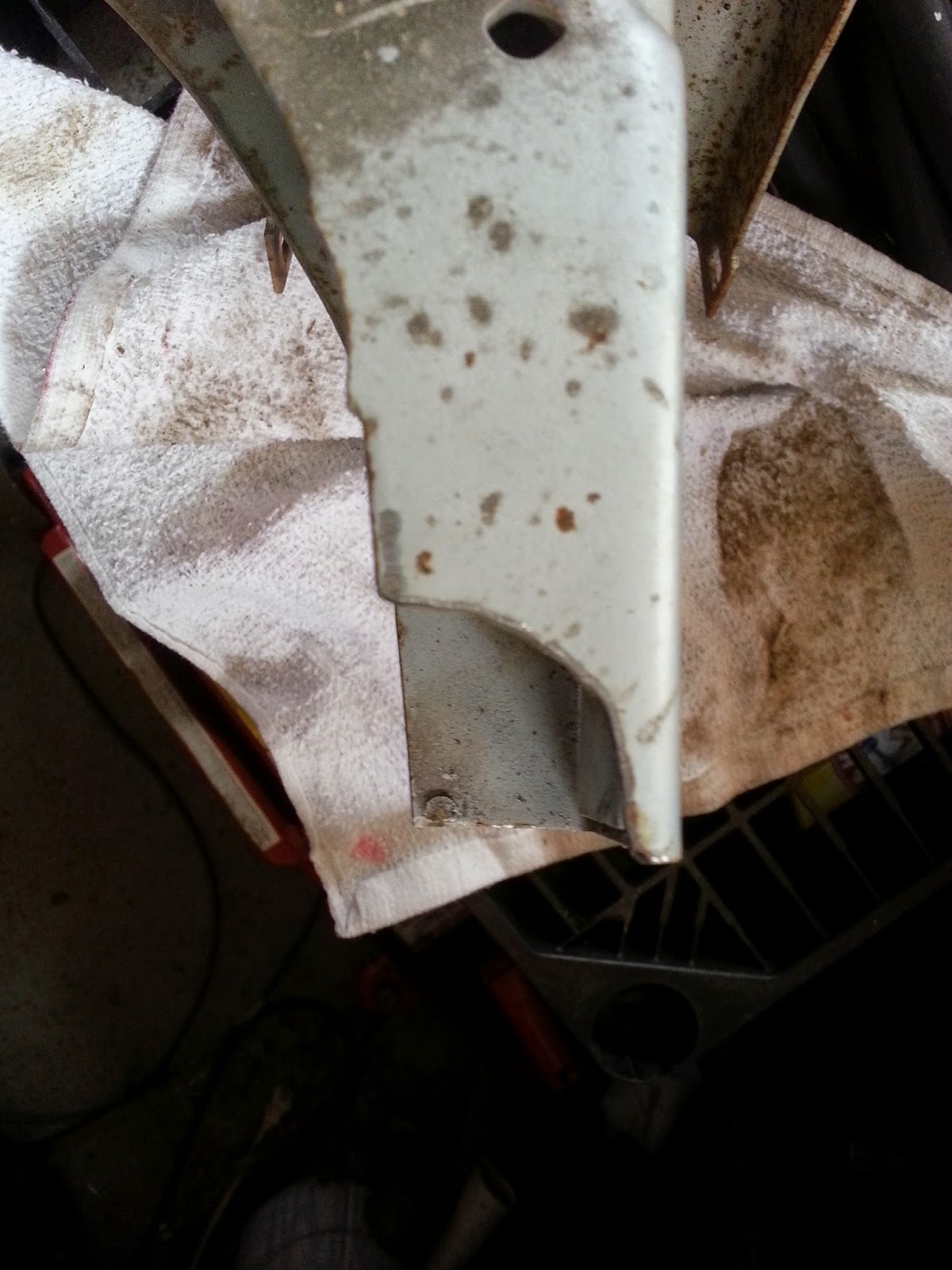
The clearanced bumper bracket. I'll be candid: this did not make me happy. Not because I think that the extra bit of steel is going to be the difference between life and death, but because the clearance is so close, it might interfere with plans I have for an eventual tow bar installed in those bracket positions. I don't see how that will be possible with this setup without having to cleverly wade back in with the grinder.
 |
| The CAT dry-fitted to the elbow, showing the amount of clearance required. |
The exhaust adaptation is by far one of the more headachy challenges that relies on some commodity products (Muffler, CAT) as well as niche production products from RMW, and neither of the solutions are ideal. It is an intensely tight fit. It works; let there be no misunderstandings. But it is awkward and needs to have a better way to crunch space to make a Bay Window fit as elegantly as it does on a Vanagon. The great news is that once you've gone to the trouble of fitting it, removing and replacing components is dead simple. The Stainless Steel exhaust manifold is extremely well made, and if there ever was a reason to replace a component, the ability to unbolt components from each other without having to revert to the sawzall is great.
There may be other designs out there which will connect to a repurposed EJ22 or EJ25, but none that are built to be emissions compliant from the word go, and none that are built to this level of fit and finish. (Fit for the engine, not necessarily this engine bay.) If you have to deal with a State which is likely to hassle you on your emissions compliance, being able to open the decklid and immediately point at the upstream O2 sensor as well as the down stream O2 sensor threaded into the CAT, this is your solution. I expect to raise quite a few eyebrows with this for everyone who still harbors the 'speed freak' assumption about engine swappers, or the 'dirty hippy' view of VW Buses in general. As solutions go, it allows you to back up to your independent Subaru repair shop and they will know where all of the important engine parts are.
There may be other designs out there which will connect to a repurposed EJ22 or EJ25, but none that are built to be emissions compliant from the word go, and none that are built to this level of fit and finish. (Fit for the engine, not necessarily this engine bay.) If you have to deal with a State which is likely to hassle you on your emissions compliance, being able to open the decklid and immediately point at the upstream O2 sensor as well as the down stream O2 sensor threaded into the CAT, this is your solution. I expect to raise quite a few eyebrows with this for everyone who still harbors the 'speed freak' assumption about engine swappers, or the 'dirty hippy' view of VW Buses in general. As solutions go, it allows you to back up to your independent Subaru repair shop and they will know where all of the important engine parts are.
3 comments:
You, sir, are my kind of nerd. The same attention to detail, desire for facts and data. By some of your comments I suspect we may even be in similar lines of work. Your conversion uses a lot of the same parts as does mine (gotta love those RMMW parts), though you opted for the belly-mount radiator while I went for an in-bay radiator setup. I think I may need a combination in the end, but we'll see. So far I can keep up just fine on an 85deg F day at 3200rpm, though 95deg may be problematic....
Keep it up. Your posts are entertaining, informative, and inspiring. I've been trying to get info out there, too, though you have me beat in terms of detail. Kudos. I'm not quite as motivated, and am leaning on an existing forum to get work out: Mick at Boxer Swaps has been very helpful here. Check it out if you get a chance: http://www.boxerswaps.com/component/kunena/air-to-water-cooled-engine-swaps/360-1979-westy-camper-conversion?limitstart=0
I'll be back here to check it out. Thanks again.
My solution was nearly identical, with a couple of notes:
1) I used the Magnaflow 12614 muffler. I can't exactly recall, but I think this was because it's a couple of inches shorter. Pro: shorter. Cons: center/center pipes--not offset. Also louder (I assume--it's a straight through).
2) I used the same cat, but my engine came from a CA-emissions car. Result is I have a persistent "below efficiency threshold" code. I'm sure it's good enough for federal, but not for CA. I don't know if the lower threshold is in the software or the downstream O2 sensor... likely both.
Otherwise my experience is the same. I had to make different cuts to my bumper brackets with the shorter muffler, but still required mods. I had a local welder TIG the cat to the muffler to a ball joint--all butt joints. Changing one of the components will be harder, but I can get the whole unit out with a few bolts.
Again... thanks. Your blog is amazing.
Great insights on car maintenance! Many car owners often underestimate the importance of timely repairs, especially when it comes to cooling systems. If you’re wondering how much to fix ac in car, it really depends on the issue, whether it’s a refrigerant refill, compressor replacement, or a full AC system repair. At Kwik Kar Auto Dallas, we specialize in Auto Repair, Car Repair and Maintenance, Engine Tune Up, Wheel Alignment, Oil Change, and DOT Inspection. Our team ensures your vehicle runs smoothly, and we provide reliable services as a trusted Auto Repair Shop. For anyone looking for quality Car Repair Services in Dallas and nearby areas, it’s worth consulting professionals who can diagnose the problem accurately and offer fair pricing.
Post a Comment