Thursday, December 31, 2015

A Pause for Station Identification..

Friends & Haters, (I attract a wide range of interested parties)

What the hell happened? Cruising along, making good progress on  the Subaru conversion, and then suddenly the line went dead. What happened?

Everything, all at once.

  • The 'C' word: Shortly after my previous post (in July!) both of my parents, within weeks of each other, were each individually diagnosed with stage 4 cancers. Stages aren't a 'clock' for when you kick it: they just describe how advanced the cancer is and if it has jumped between body organs. My father is already a partial invalid who won't acknowledge his limitations, which makes him especially challenging.
  • Kiddo troubles: I have two, and the elder has Autism. He has deep seated behavioral problems that are far worse than the Autism, and those have stalled his academic and maturing process. After a decade is a very good school system, he has proven so far beyond their abilities that we have had to move him to an institutional setting, though he lives at home. This is both heartbreaking and a great relief, as we aren't playing the game anymore that he is ever going to get or be better. His sister is heavily medicated for ADHD and behavioral, and while she is doing well in the school system, it is only by constant presence and reinforcement that she is progressing.
  • Work troubles: We've all got them. In my case, I'm standing on the precipice of ageism in an industry where (unless you are a rare talent) 40 is old. I'm rare, but I'm not that rare. Even management admits that the volume of work we're running is extreme, so work is a place of intense stress. I'm also trying to find work closer to home due to the previous three issues.
  • The reaper outside the door: We've had more friends, acquaintances and extended family either walk up to the chasm of death and lay their toes over the edge, or been snatched by the reaper, and we've been part of the support for the dying or the survivors.
  • My own health: Not so good, and made much worse by severe stress, which you can see is the only thing I have in abundance. Possibly growing my very own hiatal hernia. Psych counselling to make sure that I don't collapse under the load already present.

In lieu of the bus, you can see that my dance card is full. Hell, I don't even have time to watch a lick of TV with my wife: I've given up all of my favorite programming because there hasn't been a 'day of rest' in half a year.

This does not mean that I have stopped (I haven't) or quit (bite your tongue!) or given up. (Say that again, and there will be blood.) I just don't have time to blog about every little scratch on the project. Here's the omnibus version:

  • After going through electrical hell with what I was assured was a good battery, and having bought a new starter, second guessed all of my wiring..come back to find I have a bum cell that wasn't cause by the Autozone eval machine. $90 of new battery sorts that. The calculatus eliminatus process takes 10 weeks though, since I'm wading through everything else (see above) at the same time. The engine turns over.
  • New Alternator belt 273k5 or 5pk0690.
  • A new Blau fuel filler cap.


If it doesn't sound like much, you're right. It has been a heartbreak to watch others who started years after me out running around in their conversion having fun. When you try to make and document a conversion anyone can do, it is a much higher bar than just scratching your own itch. So I'm trying to give myself some grace there.

So that's where I'm at. What will 2016 bring? I've no idea. Never say, "Things can only get better." Bull. They can always get worse, too.

Instead I choose to say: Let's go see what's over that hill...

Wednesday, July 8, 2015

The Hose Knows

Working on a hybrid of 20 year old Japanese Subaru technology and 40 year old German Volkswagen technology in a metric hostile country can be maddening. Most of the time, you can get the parts that you need from a dealership...for the Subaru anyway, if you know exactly what part number you need. For doing an adaptation, you're going to need a specification list to know what sizes and types of hose you're going to need to buy.

Ordering by part number will improve your chances of it fitting a stock installation, but there won't be any information about the physical properties: Length, Inside Diameter, Outside Diameter, and material specifications (fuel, oil, EVAP vapors, coolant, etc.) If the part happens to be a hose and is No Longer Available (NLA), getting accurate measurements from one which has been in service for 20 years or more is often fruitless: Rubber shrinks as the volatiles in it leech out, so you can't be fully sure of the size of the hose you need. This is where you can really run the price of a conversion through the roof: having to buy one of everything, in every size, because you don't know what you need.

So even if you hit the jackpot and a molded hose is still available, that won't help you if your adaptation has rearranged the orientation of components the hose was meant to connect to. Then you must revert to using generic hose and determining its Inside Diameter by measuring the Outside Diameter of the fittings with a caliper. Once you've got a Metric measurement, convert to U.S. Customary (aka "Standard"), because for generic hose types, fractional inches are all your going to be able to find here in the Land of the Free and the Home of the Pig-Headed.

Units of Measurement in the USA don't have a proper acronym. No, not SAE (Society of Automotive Engineers) or even a simple 'Imperial.' The UK (from which 'USA Standard' is derived') standardized their weights & measures in 1824, and metrication begun in 1965 is still ongoing today. The United States is still doggedly and self-importantly stumping along on a system from the Middle Ages: A mongrelization of German tribal units and Roman units enforced on the English population by William the Conqueror after the Norman Conquest in 1066. 

My Country Tis' of... Nevermind.

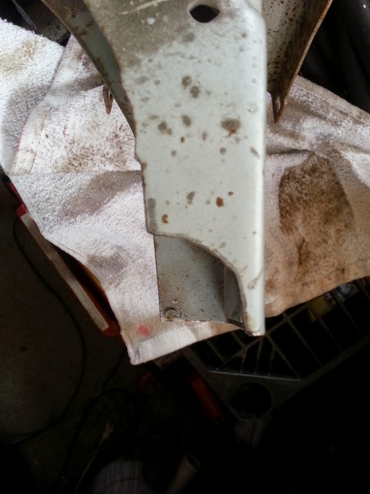
This is what "traditional" hose for a vintage VW looks like after a year
of pumping 10% Ethanol. This is a wonderful way  to burn your Bus.
I'm going to toggle to fuel hose quality for a minute here, discussing both available sizes and fuel permeability (how much the hose 'sweats' fuel volatiles right through its skin which leads to degrading hose.)

If you're trying to use modern hose material available in the USA for your vintage VW, you'll probably run into the old school nuts who insist VW expects you to use the 'right' hose: In a Fuel Injected Bus you should be running the 7mm hose, since even the fuel hose is 'engineered' to stretch just the right amount to make a good seal around a slightly (.09mm!) larger fitting.

Let me just say this once: No vendor makes modern Fuel Injection safe, ethanol compatible fuel hose in 7mm. You can find them in the right size from overseas sources, but those hoses are not Fuel Injection pressure rated and allow gasoline in them to vent right through the hose walls about 33x more than modern hose.

How ironic that the more militant a vintage enthusiast is about the look and exacting size of a hose, the more likely they are to burn down their own Bus from using poor materials. (Passions run high on the subject of fuel hose.)

The sizing issue is partial hogwash. Yes, if you aren't careful, you can do something stupid and ruin your car. Put hose that is oversized for the fitting (because you are too careless to convert Metric to USA Standard) and the most monstrous hose clamp in the world won't keep it from leaking. Now add a third variable (Subaru fittings) and finding the right hoses for your adaptation can get complicated fast. I do pity the folks who need to use a 5.5mm hose: There is literally nothing on the market for them.

VW & Subaru prefer different standard metric sizes (VW: 3mm, 5mm, 5.5mm 7mm, 11mm // Subaru: Anything BUT the VW metric sizes.) What might be made to fit on the VW side still fits sloppy on the Subaru side. Or vice-versa. Regardless, you still have to go shopping in Fractional USA Standard measurements.

Depending on what you're putting through a hose, you can sometimes outwit this Machiavellian conundrum. I did one today: The brake booster. The Subaru side is 10.12mm at the fitting on the intake manifold. The VW side is 12.33mm on the fitting at the body that runs to the front of the vehicle and the vacuum booster. The fittings are on opposite sides of the vehicle.

Nota Bene: Hose, no matter what is transferred through it, should be chosen by specification for the job. Find out what you need and buy it. Don't use a 1/2" ID chunk of garden hose on your car because 'its what I had lying around the garage.' This line of thinking leads to disaster.

Yup. Maddening. Here's how I outwitted it:

The closest that I could get on the VW size to that 12.33mm is to convert to USA Standard, and then choose the next smaller size. In the case of the vacuum hose, forums like thesamba.com have been singularly unhelpful. No one seems to have an actual source for the power brake vacuum hose, or truly know what the material requirements are. I have had it recommended to me to re-use the 40 year old hose "because we know that works." Which is great...if you're doing a 40 point Concours Restoration. A brittle, 40 year old plastic hose of unknown material is not a smart bet for holding vacuum for another 10 years, let alone another 40. The old school mentality which used to decry form over function is now doing so in the name of 'we know it works.' This is a sign of dotage: All it really means is 'twenty years ago, we knew they still worked.'

So here's what I've learned: The properties of a hose designed for both vacuum and pressure are very similar: They tend to have thicker bodies, multiple layers, and spiral braiding. They also don't take well to tight radius turns due to their thick bodies. A thinner hose kinks; the thicker hose will just refuse to play.

So having measured your fittings, let's walk the math:

VW side fitting: 12.33mm x .03937 (converts to inches) = 0.4854321

Ugh. Decimal inches, the worst of both worlds.

Thank God for conversion tables. They include regularly spaced fractional equivalents, the only way most of the knuckle-draggers know how to sell things here in the U.S. of Pig-Headed. If I work my way down a chart, the first stop down below 0.4854321 which has a usable fractional equivalent is .46875, or according to my table: 15/32".

Mercy me! Gates just happens to make a 15/32" power brake vacuum hose. P/N GAT 27233

That does the VW side. Now I have to do the Subaru side of 10.12mm at the fitting.

Subaru fitting: 10.12mm x .03937 (converts to inches) = 0.3984244

Hmm. First stop down on the table yields the unlikely size of 25/64 (.39063"). Nobody sells anything in that size. But one very tiny stop down the table from that at .375" is dear old 3/8". In USA Standard, they sell everything from coffee to condoms in that size. But not power brake hose from Gates.

Still, finding heavily reinforced hose is not hard in a 3/8" size. You can get away with it in this case because the only thing the hose needs to contain is A-I-R. No concerns about material suitability for fuel, coolant, hydraulic fluid, etc. Yippy!

Nevertheless, you'll have to dig for it since your local franchise parts shops are unlikely to have what you need and because they want a make/model/year of your car, they have no way to look it up by specification, instead of by application. Requesting "Seven feet of 5/16" SAE30R14r2 fuel hose" is only going to earn you a dumb look. NAPA is often the only chain where you can order a part by its specifications, and it is still safer to walk in with a manufacturer name and part number than the raw specs. Local or online Speed Shops may be other places to buy by specification, even if you aren't interesting in building a racer: They're the only ones who still speak the language.

I'm just moving air: a brass adapter for the power brake
vacuum hoses isn't any problem at all.
In my case, I'm using PVC jacketed 3/8" ID reinforced rubber air hose, aka the stuff that's designed to take about 300PSI of pressure from your industrial air compressor. So I've got both the Subaru end licked, and the VW end. There's just one problem: The different size hoses still have to join up in the middle.

My solution was to use a brass fitting adapter: Male/Female threads in between with 3/8" male barb on one end and 1/2" male barb on the other. Screw those pair together with teflon tape and a dab of blue lock-tite, and you have an adapter for about 8 bucks. All told, I fabricated this unobtainium variable size hose built to take heavy vacuum and not fold up for about $24. I had about $80 of my TIME researching source material for it, which is frustrating. But my time is already spent and I've shared my results, so at least you shouldn't have to waste your time, too.

The adapter in place: 15/32" to the right of the adapter, 3/8" to the left back
to the intake manifold. NOTE: The 15/32" section is NOT bent: That is a
molded curve in that piece of hose. B/W picture because the PVC jacket on the 
air hose is exactly the color GREEN of a garden hose, and I don't want 
someone making a foolish assumption.
So what do I do about those little size mis-matches? The ones that the well meaning old school says will make my VW BURN if I try this with fuel hose? They object to a hose which isn't exactly undersized from the VW fitting than VW says it should be. Their assertion that stretching the wrong size rubber fuel hose will just split the rubber: leak, ignite, burn. This remains true now...if what you're using is just Continental Brand cloth weave covered rubber hose, just like grand-dad used on his VW.

Today we're using different types of hoses which have a fluoro-elastomer liner on the inside diameter. The rubber can stretch these kinds of hose over a slightly larger fitting without fear of them splitting and bleeding out all over the place: The layer that takes the brunt of the stretch is the extruded liner of the hose. Because of the separate layers, you're unlikely to split the way a single layer extruded rubber hose might. The PVC layer on the outside aren't in contact with the contents: they're just there for mechanical reinforcing. The interior liner takes all of the abuse from the E10 gas or whatever unsavory thing you pump down it. Even hoses which aren't transporting fuel are moving to this multi-layer design with an separate inside liner for the hose.

My stunt for making slightly undersized hoses go on the slightly too large fittings is simple: a deep travel cup of boiling water, and foaming anti-bacteria hand soap. No kidding.

This Performance Electric P37 fuel pump from Sweetwater, Texas is
a better stand-in for the stock Bosch pump: It permits the removal of
the pre-filter and allows me to run a stock Subaru filter in the engine
compartment. Both fitting accept 5/16" hose which fits the
Subaru engine fittings (8mm) nicely. Use VW #: 111-941-539 boots 
to cover the spade ends for the power.
Pop the end of the hose that you intend to attach to a fitting into the boiling water and let it set for about 10-15 minutes. The warm up time is to give the normally non-stretchy materials permissions to 'get loose.' You'll want to wear gloves for this, because that hose will be HOT when you pull it out.

When you're ready to pull out the hose, first use the hand soap to lube up the fitting. Then pull the hose out of the hot water and give it shake to remove excess water from the inside. Then add your hose clamp. Now push the hose over the fitting. Between the heat giving the materials a new-found willingness to stretch, and the lubricated fitting, your hose will likely go on with a firm, steady pressure. Now tighten down the hose clamp while the hose is still warm. Finally, if you need to make bends in the warm end of the hose to clear occlusions or to lay the hose into guides, do so now.

As the hose cools, if everything is kept under compression (like a bend or something) the hose will shrink down to its former size and stiffness, except now it will have conformed itself to the fitting and the turns you have forced into it. Remove it from its guides, it will want to go straight again. Left alone however, you'll probably never have to touch this fitting again. Even the water in the soap dries out, leaving a sticky residue that tends to seal the connection even better. It will make it quite difficult to get the hose off the fitting in the future, but unless you're replacing engines or components frequently, this is an acceptable trade-off for the daily driver.
This is not the guaranteed outcome of using non-metric hose on your Bus.

What are the products I've used for my adaptation? I've linked the specification list as a separate page which will grow as I finish the project. While it might be more expensive to use a product that is designed for more than the minimum specification to do the job, sometimes you can only find the size of hose in Fractional USA Standard that you need in a higher rated hose. You might use a fuel hose that is a better size match for an air hose which is not available in that size.

So look over the spec list! There are only two times a hose can be 'wrong' for a conversion: When it won't fit right (seal) and when it isn't made of the right stuff to do its job for 20 years. Make the effort for it to do both. Imagine the horror when you complete your conversion project....only to burn it down or wreck the engine because you used 'the wrong hose.' Look at the specs.

Tuesday, June 9, 2015

A Rainbow of Wiring

"A pox on both your houses!" 
- Mercutio, Romeo & Juliet ActIII, scene1

I cannot say how much I hate wiring. Well, actually, I can...but not unless I censor it heavily for this blog.

I'm not scared of it, mind you. Dad first set me up wielding a soldering gun and made me practice making good solder joints for electronic applications when I was seven. I've been doing my own stuff for a long time and I don't think there's a car I've owned in 30 years that I didn't wire up like Hi-Fi freak's basement when it came time to put tunes in.

Automotive electrical doesn't scare me either: 2 months after I had driven my 1977 VW Scirocco coast to coast for college, I tried to start up one chilly morning and got nothing. So I started my father's classic diagnostics: "Fuel, Fire, Air." Those diags led me to pay-dirt in 2 minutes flat, which was good because I didn't even own a multi-meter at the time: Turned the key to run, and heard...nothing. I should have heard the fuel pump by the left rear wheel come on. I'd only owned the car for 5 months, but I'd read the repair manual cover-to-cover as a sleep aid. I hot-wired ("jumpered") the pump power on, confirming that the busted part was the pump relay and drove the car into town to lose a week's income for a new relay.

So I ain't 'fraid a no wires.

From 1949 VW used a pictorial style of wiring diagram and it gave you a sense of not only what the wiring path was, but also where the components were within the chassis. as well as a literal line drawing of the starter and even where to connect what wire. DIY bliss.

While busy, the diagram is readable. The components are accurately drawn, and there are no nutty surprises.
In 1973 VW changed to a schematic diagram style which showed only a common ground and symbols for the components. The diagrams went from readable to migraine inducing. I'm not the only one. I've offered them to many of my friends who are Electrical Engineers and they've stared at them and to a man, all have said, "Well, it might be accurate but this is almost impossible to read. I wouldn't want to work on a system that required using this as a guide." Uh, oh.

A part of my soul just died.
Because of the schematic style, the wipers, starter, heat blower fan, and fuel pump are all represented by the same symbol. (There's a cookie for anyone who can think of what all of these things have in common electrically.) There was a separate key published for what component each symbol represented (in case you didn't have an EE degree) and a reference to what "current track" to ground it was on. You had to click your eyes back and forth between the schematic and the key of over 100 different components to puzzle it out. There was also no sense of proportion: A switch might be located between a component and the ground and the whole line be only an inch long, but the true distance in the vehicle is a wire running all the way from the dashboard to the engine at the rear.

A raging nightmare...unreadable.

By the way, the aforementioned are, electrically speaking, motors. So they all look just the same, diagramatically:

In 1979, VW realized their mistake and began adding pictorial style components back in to the schematic diagram, even captioning some of them within the diagram. A 1979 diagram is close to my 1977, so I often consult the 1972 (pictorial), the 1977 (schematic), and the 1979 (hybrid) all to make sure that the wire I'm staring at in the half-light really is Blue/Red, and not Blue/Black that has faded with heat and time and really is supposed to be attached to the alternator idiot light.

In short, the diagram is barely readable, the color coding often insufficient to communicate meaning, and the whole harness supports a primitive EFI system (Bosch L-Jet) where the ECU is only smart enough to squirt fuel relative to air intake. Every other part of the EFI sub-system is uncoordinated from the ECU. As a systems designer, this whole thing makes my gut go cold: So many ways for it to go wrong, both catastrophically and subtly.

Now replace the engine, EFI system and uncoordinated components with a Subaru and its much smarter brain. Have a kindly Subaru wiring harness expert make trims to remove all of the unnecessary items and send the Subaru harness back to you with the admonishment: "Three wires: 12v battery, Key ON, Fuel Pump. If you can't figure out where to attach three wires to your vehicle chassis harness, I can't help you." He's right. How hard could it be?

Harder than it looks. Subaru harnesses are notorious for subtle differences from month to month, let alone from year to year and model to model. Maybe Subaru has some serious quality control issues in their wiring assembly division, because sometimes the signalling wire from the whatsit to whizgig is Blue with a White stripe...or Red with a Yellow stripe, or ....Brown. Consult the factory service manual for the model, year, trim, and market  (Impreza MY1997, Outback Sport, LHD USA) and that diagram says the wire in question should be Chartreuse with an Indigo stripe. Oh, hell.

Usually such headaches hurt less with a Subaru because everything terminates at a fitting, and every fitting is shaped so that it can only connect to a specific component. The electrons don't care what color the insulation is, so why should you? You're guaranteed that you can't plug in to the wrong place.

Until you cut the harness. Then that certitude is lost. Now try to graft it to a chassis harness designed to support an uncoordinated Solid State EFI system only slightly more complicated than a transistor radio to a reasonably modern ECU which pretty much requires 'three wires' to make it go.

The good news is that some things don't change. Both systems use the positive stud at the starter motor as the primary junction for the chassis harness, the ECU, the battery, and the alternator output. Both systems use the chassis as a common ground. Both systems use 12 volt power. The bad news is that those are where all of the similarities between the two systems ends.

My harness man is right: If you can't figure out where to hook up three wires, maybe you're in over your head. I know what the big three need to DO, I know what the electrical path is for them to do it, and I know what the switching path is (at the front of the vehicle on the other side of where you turn the key.) What I'm having trouble unravelling is VW's baffling diagram, and which parts of the factory EFI interface I can ignore, and which ones I must route around, and which ones I have to live with.

Sidebar: When it comes to systems (technological, religious, ethical, philosophical, etc.,) all of them have fundamentals that are the starting point for everything else. This reductivism is helpful, because they restrain adherents who inevitably wish to complicate it. An example would be Jesus' directive to love God first, and then love others as much as you love yourself. Others include The Five Pillars of Islam. The Four Noble Truths of Buddhism. Asimov's Three Laws of Robotics. Ken Thompson's 3 Rules of UNIX Philosophy. All systems with a limited set of starting rules. The fact that they're systems conceived for completely different purposes is irrelevant.

The T2B VW Bus electrical system has three fundamentals:
Suitable for framing, while doing VW wiring.


  • Terminals #30 are ALWAYS powered, even if the key is OFF.
  • Terminals #15 are only powered when the key is in the 'run' position.
  • Terminals #50 are only powered when the key in the 'start' position.


Notice these are "Terminals" or connection points, not the wire in-between. It comes to the same thing as long as the wire doesn't join or branch. This should make everything much simpler. By convention (certainly not a guarantee, but good enough to guide you if you Trust But Verify) each of these is color coded:

Red is always #30 (12v, unswitched.) If you see a pure red wire, it is tapped back to the battery and is live all of the time. Other color wires may also be #30 (Red/White) so this is not a 1:1 relationship. #30 is often but not always R/R, R/R is ALWAY #30. (R/W is the trunk line power to the fuse panel and therefore, everything under the control of the driver. As soon as it joins the panel...back to RED.)

Black is always #15.  Unlike #30, #15 is always a conditional source: they key must be in 'run' to make #15 live. #15 then distributes power to other sub-connections. Find any component that only works when the key is in 'run.' Stare at the wiring diagram. Stare harder: even if you have to jump through a few conditional switches, you WILL find your way back to #15. An easy example is the back-up lighting.

#50 is always Red/Black. Thankfully, there is very little of it. It's pretty much a single wire with two ends and no branches: One at the ignition switch where it receives power from #30, and one at the starter solenoid. When you turn the key to 'start' the switch closes between #30 (R/R) and #50 (R/Bk) and the power hits the starter solenoid which pulls the starter gear into place. The starter takes care of it's own heavy Amp power switching itself. When the engine catches and you let go of the key (which falls back to 'run') #50 is disconnected and the solenoid retracts the starter gear. Now in 'run' (#15) everything that is #15 dependent is available.

Soon I'll give you a better idea of what the actual 1:1 connections are between the T2B Bus, and an OBD2 Subaru ECU. It turns out, the major challenge is knowing what to IGNORE.

Tuesday, May 19, 2015

Exhausting Work

It has been three weeks since I got any appreciable work done on the Bus, and it is irritating the life out of me. Not that there is much I can do about it: The latter half of my vacation week was taken up with family duties surrounding Easter, and when I walked back into work the next Monday morning, all hell had broken loose in my absence. I'm not sure this vacation thing really works for me: If I take a week off, I don't have a week's worth of work waiting for me when I return, I have five weeks worth of work, so it has been 14 hour days for more than a month, such that I return home wrung out like a damp rag. This doesn't seem like a fair trade-off. So five weeks later, I'm finally starting to see the waves above me and hope to break the surface soon.

That said, I had a pretty un-memorable time working on the Bus' retrofit by way of Rocky Mountain Westy products. This isn't a dig at RMW, it's compliment! Most memorable experiences I have when wrenching are BAD memories. So 'unmemorable' is the highest compliment I can give.

Most of the RMW solutions are straight up bolt-on. During the week when I could work, I got a lot finished: and even more mocked up. Instead of just telling what I did, I decided the best use of this blog would be to show and comment, rather than describe to death. In this installment, we'll review the Rocky Mountain Westy Stainless Steel Exhaust system.

First installed are stand-offs that the heat-shield / muffler support mounts to. They replace the cam belt cover bolts. If you can't manage this part, you should probably not be working on your own car yourself. Also, you should probably get someone else to brush your teeth. (Tech Tip: Juice up the old cam cover bolts the night before with PB Blaster so you don't round off the bolt heads. Don't use an adjustable wrench or even an open end wrench: use a socket. This is not a component that you want to get stuck.)
The standoffs come with letters stamped on their bodies and a diagram for which cam cover bolts each one is to replace. This is paint-by-numbers, made easy for the DIY installer.

Heat shield mounted on standoffs. Note un-used vertical holes to the right (for muffler bracket and strap) and to the left (for EJ25 engines which have additional points which may accept standoffs.) One part that works for both engine applications.

The standoffs hold the heat shield away from the plastic timing belt cover just enough to protect the cover and provide a finger-width distance from the crank pulley. It is a safe clearance, but replacing a belt would be cramped, and replacing the crank pulley itself would require dismantling the entire exhaust system. Still, that isn't a part that you're likely to replace on a whim. If you just MUST get your bling on with a new crank pulley, install it before you add the exhaust components.

Having bolted down the exhaust heat shield to the standoffs, I added the powder coated steel bracket for the 6" round Magnaflow muffler. Whenever possible, I flip the fasteners around so that the bolt head represent either the least ground clearance or hide the nuts and threads for aesthetic purposes. In this case, only the bolt heads are visible because they're facing to the rear where you look in at the engine: the threads and nuts are still accesible from above where you can't see them unless you climb into the engine compartment. Suffice it to say, the bracket hardware remains accessible while not flashing the less lovely bits to the public.

Powder coated 12ga. steel bracket bolted to .080 Corrugated Aluminum heat shield. This bracket is specifically designed to support the 6" diameter Magnaflow mufflers, though there is scarcely room in the cavity for anything else. The Subaru design expected to put the exhaust UNDER the engine, 
The T304 exhaust manifold for the right hand side exhaust port.
RMW provides exhaust for both single and dual port EJ engines.
Having installed all of the support materials, I started on the exhaust manifold proper. Also T304 Stainless Steel, all of the RMW manufactured mandrel bent tubing (coolant and exhaust) came with their ends capped to keep debris out of them. Excellent attention to detail and beautiful TIG welded joints and fittings.

The secret sauce for assembly is that the whole system is modular. Some folks have expressed nerves about slip-fit exhaust. If the whole thing were just held in place 'slip-fit' I'd agree. Instead, it uses Stainless Steel Torque-tite band clamps and the slip-fit joints are two inches deep (except for one, which I'll get to.)

The exhaust manifold prior to the CAT is a serpentine thing that each leg joins, then exits to the left, then swings back toward the right side via a 180° elbow to bend the exhaust flow up into the engine bay. The 180° elbow has a bung in it that the up-stream O2 sensor can be mounted in. In my case, I'm interested in the delta between the O2 values pre-CAT and post-CAT since my ECU has the capacity to measure both. (Recording the delta between the two lets you see what the efficiency of your CAT is and when it begins to fail. Some folks go without the upstream and just record the downstream values, tricking the ECU into thinking that the emissions are cleaner than they really are.)

You can assemble the lower portion of the exhaust manifold, and then work the whole thing up (according to packaging instructions) with muffler cement. Goop up the inside of the larger ID slip fit, then assemble and loosely add the torq-tite clamp.

(Note: Before you go cranking bolts down on the exhaust studs, make sure that you can get a properly fitting exhaust nut all the way up and down the stud; used studs are often pretty rusty or corroded. Running this simple exercise BEFORE you try to mount the manifold might make your life a lot easier just in the confidence of knowing that you can add new exhaust nuts to the existing studs and know that they'll come off again without snapping off the stud. Plenty of PB Blaster and some quality time running the new nut up and down the stud is worth a world of confidence when it comes to the final fit-up.)

Get the assembly under the car and bolt up to the exhaust ports, remembering to sandwich the gasket in between the manifold and the port. Tighten down your exhaust stud nuts to finger tight, such that the whole shebang wants to stay in place. Once both sides are done, wiggle until both sides are aligned, then add the torque-tite and tighten down on it until it wants to hang on. Torque-tite bolts are 14mm.

Run the same procedure for the 180° elbow. (It should still be able to pivot at both ends when finished, as you'll need to pivot around both the top and bottom portions of tubing and components as you rotate the assembly into final position.) This moves us to the top of the stack: The CAT and the muffler. Predictably, this is where it get interesting.

The muffler is the reversible Magnaflow 16450, a 6" round 18" long body with 3" long input / ouput pipes which are both offset from center on opposite sides. That CAT is also a Magnaflow unit.

This picture is a wealth of information: All of the slip-fit portions are dry fitted together and you can see some of the modifications that had to be made: 1) The left rear bumper bracket had to be clearanced, 2) The sequence of slip fit components means that each component added should have an input larger than the output. 3) the upstream O2 sensor visible behind the tubing elbow is screwed into place, 4) The muffler is BIG when lifted high into the space, necessitating the heat shield. All components are T304 Stainless Steel.
This is sort of the Achilles heel of the installation for people who want to run and gun. The components require modification for use in a Bay-Window Bus, the kit having been originally designed for the much wider Vanagon. There just isn't the same amount of space to fit the whole stack of the elbow, CAT and muffler into the narrower space available without some modification. It isn't short by much, but it's enough to cause problems that will stop the project dead in its tracks: The muffler is too long to fit in the space comfortably. The body occludes the muffler at the right rear when the muffler clamped into the support we saw earlier. The only way that this 'almost, not quite' solution works is by some judicious trimming in the right places. The following are the steps that I took to deal with it, steps that anyone with a $15 grinder and a nearby muffler shop can cope with.

First, we'll bob the inlet of the CAT, a Magnaflow 53034 recommended for this installation:
Take your die grinder and remove 15mm of the inlet end, e.g. the end opposite of the O2 bung. When you fit the CAT into the flared end of the 180° elbow, it will now shift 15mm to the left.


Take your muffler to a reputable muffler shop and have them stretch out either end (but not both) to accept the CAT's 2" OD outlet. Since one now fits inside the other, you just bought 25mm of width back. Best to take the CAT with you for a test fit. it should be as close a fit as you can manage.

Here you can see the outlet of the CAT (left, with O2 sensor above) INSIDE the stretched inlet of the muffler (right). Fitting one inside the other  buys back another 25mm, again shifting the muffler to the left. But now you must clamp these two together to make a seal: you can't 'unstretch' the muffler inlet pipe. Welding (since it is Stainless Steel) would be with TIG: Expensive. Instead, we'll make our own ersatz fitting.
Using the cutting wheel again on the inlet, cut 5 parallel relief cuts 20mm long equidistant
around the pipe, just short of where the pipe flares out to its largest diameter.
(If you pass that line where the pipe flares out, you'll never get it to seal. So don't botch it.)

Now you finally have the option of getting a clamp around this stinker and crimping down on it. As before, I used muffler cement liberally since this is the most likely spot (due to the relief cuts) for there to be leak. So I gooped up the inside of the muffler inlet and then inserted the outlet of the CAT all the way inside. Then I added the clamps shown below.

I used a basic set of 1-5/16in" to 2-1/4" dia adjustable  Stainless Steel clamps sourced from my local Lowes. (PN 48536.) The mating area is thoroughly gooped up with muffler cement, and the clamps worked down tight. Between the friction fit, the clamping effect of the adjustable clamps and the pressure of tubing which can collapse and seal the better for the presence of the relief cuts, this should be a well sealed connection.

So judicious trimming bought back enough space to be able to slip-fit all of the parts together and pull the right end in considerably. Total up all of the trims, and the muffler moved more than 1-1/2" to the left. But we're not quite through yet: We're going to shift the 180° elbow to the left, too, which will move the whole upper stack to the left by enough to allow the muffler to clear comfortably.
To shift the upper stack to the left, a compromise must be made at the bottom slipfit joint of the elbow. The elbow permits about a 2.25" overlap of the slipfit which is then covered by the 2" long Torqtite band clamp. To shift the whole upper stack to the left, I overlap the exhaust manifold by only 1.25" and then put the 2" bandclamp in place. 
This solution does not thrill me, since the elbow now hangs out to the left and forces me to clearance the left rear bumper bracket. Short of a re-engineered exhaust manifold, it is the only way to move the upper stack (CAT & muffler) the last full inch for a total of a 2.5" shift to the left for the muffler. This is just enough to allow the muffler to clear the body and still have a finger width of clearance.


The details of the trivial trim. No plasma cutter required, just an obnoxious
swipe with a sharpie to follow, and some  sacrificial cut-off wheels for my grinder.
The clearanced bumper bracket. I'll be candid: this did not make me happy. Not because I think that the extra bit of steel is going to be the difference between life and death, but because the clearance is so close, it might interfere with plans I have for an eventual tow bar installed in those bracket positions. I don't see how that will be possible with this setup without having to cleverly wade back in with the grinder.


The CAT dry-fitted to the elbow, showing the amount of clearance required.
The exhaust adaptation is by far one of the more headachy challenges that relies on some commodity products (Muffler, CAT) as well as niche production products from RMW, and neither of the solutions are ideal. It is an intensely tight fit. It works; let there be no misunderstandings. But it is awkward and needs to have a better way to crunch space to make a Bay Window fit as elegantly as it does on a Vanagon. The great news is that once you've gone to the trouble of fitting it, removing and replacing components is dead simple. The Stainless Steel exhaust manifold is extremely well made, and if there ever was a reason to replace a component, the ability to unbolt components from each other without having to revert to the sawzall is great.

There may be other designs out there which will connect to a repurposed EJ22 or EJ25, but none that are built to be emissions compliant from the word go, and none that are built to this level of fit and finish. (Fit for the engine, not necessarily this engine bay.) If you have to deal with a State which is likely to hassle you on your emissions compliance, being able to open the decklid and immediately point at the upstream O2 sensor as well as the down stream O2 sensor threaded into the CAT, this is your solution. I expect to raise quite a few eyebrows with this for everyone who still harbors the 'speed freak' assumption about engine swappers, or the 'dirty hippy' view of VW Buses in general. As solutions go, it allows you to back up to your independent Subaru repair shop and they will know where all of the important engine parts are.

Saturday, May 9, 2015

Coolant's Full Monty

I've got all of the Rocky Mountain Westy designed cooling loop in place, from the engine output all the way down to the heater wye hole in front of the torsion bar and back to the thermostat side of the Subaru EJ22. I've got busted knuckles and I'm grinning like a madman. Someone finally got it right, and damned if I'm not the beneficiary!

For those of you coming in during the Intermission, here's the quick recap: The bright lads at Rocky Mountain Westy produced a beautiful vehicle specific stainless steel coolant tubing kit similar to what they provide as replacement components for the Vanagon's oddball plastic coolant tubing that runs the length of the vehicle. Through some polite discussion with the owners of RMW, and a willingness to be the guinea-pig as they worked the kinks out of beta testing and making it ready for production, I got hold of a set of these lovely mandrel bent tubes, fittings and miscellany required to move coolant down to the heater wye area in front of the transmission nose-cone.
We're focusing on all of the stainless steel coolant tubing in the left third of the above diagram.

I have my own engineered solution for the radiator and cooling, but needed the components in the engine bay to be reliable. While I'll only briefly touch on my radiator solution in this post, I did want to show off the beautiful and clever work that RMW has performed. The idea that underlies their design differs from every other one I've seen: It's called "Nobody Move!"

What I mean by that is the worst, yet most common attribute of conversions is the use of generic/universal/cheap components, fitted one to another like tinker-toys, just enough to make a path to the radiator and back. A reasonable car buyer who looked under the hood of a new car and saw what is under the decklid of most engine conversions would scream like a sheep in that Superbowl Sprint commercial. (I won't insult your intelligence by linking it. If you want to hear it so bad, Google it.)

Instead, the RMW coolant tubing design is a delight of components rigidly aligned in the engine bay, and when their support transfers from the engine to the chassis, there is a flexible coupler interspersed to make both fore and aft sections rigid relative to the component that they're connected to: Engine supported at the rear, chassis supported at the front leading down to the heater wye.

So let me lead you on a tour of the system. For clarity, I'll be using the orientation definitions in the classic How to Keep Your Volkswagen Alive by John Muir: "Front is Front." When working on engines which face you when installed backwards in the vehicle...people get 'front' confused sometimes. My descriptions are based upon the alignment of the vehicle. Thus forward is toward the front, rear is to the back, and so on, use your imagination: behind, in front of, left side, right side, etc. I don't use the terms like driver's side, or passenger side or 'nearside' or 'offside': They are without a referent and are confusing. Everyone can do front, back, left and right. I DO use two nautical/aerospace terms for which there is no suitable substitute on a car: inboard (closer to the centerline axis of the vehicle) and outboard (closer to the exterior of the vehicle.) This way I can say that the vehicle speed sensor signal wheel is bolted to the inboard left constant-velocity joint. And you should know where that is, exactly.
Outlet from the coolant manifold at the top left of the engine, with hot
coolant passing through a coupler and into a 130° clockwise
rotation which sends the coolant forward down the left side of the
engine bay.


Looking left down the aluminum heat shield, we pass the first hard
mount to the engine. These "T-bolt" clamps put a threaded stud
perpendicular to the side of the tube. When tightened, they both clamp the
tube (placing compression equally around the circumference) but also
create a handy 1-1/2" long thread which may be used to secure
them and the tube to other objects.

Since this is experimentation time with the components that I was
sent by RMW, I felt a certain freedom to try different methods to
 secure the tubing. In this case, I chose to use the mounting tang
to attach to the heat shield. The shield doesn't really bear any weight,
it just restrains the tubing from moving.


Looking forward down the left side of the engine, the tubing transits 
inline with the engine and then jogs inboard , tucking somewhat in 
front of the engine to clear the body cavity of the engine compartment.

Looking forward, After the jog inboard, the hot coolant pipe straightens
out as it passes the transmission. When it reaches near the nose cone,
 there is a silicone coupler that separates the rear, engine mounted tubing
from the forward leg which is supported by the chassis. The flexible
coupler isolates vibrations from the engine from shaking the whole
tube, and vice versa: chassis movement is isolated from the engine.

Hot coolant tube and torsion tube viewed while facing forward, 
detail of previous picture. After passing the coupler, the forward left length 
of tubing passes over the torsion bar tube. This needs to be secured in 
such a way that the tubing doesn't press up against the body above, 
or the torsion bar below. It must pass through the area above the torsion bar 
with 1/4" (6.3mm) to spare above and below. The secret is in the bracketry
 which again ties on to the t-bar clamp so that the tubing stays where 
you put it. The tilt in the bracket allow the tubing to be pressed inboard, 
directly over the left rear trailing arm joint.
Without the bend in the bracket, this wouldn't be possible.

The brackets clamp around the torsion bar tube so that the forward section
 of the hot-side tubing is held rigidly in place. It's best to keep the fittings
 all a bit loose while connecting everything.


Here is where the hot side terminates, just behind the rear transverse support heater wye cutout. 
(Out of frame, to the right,) I found that by loosely putting all of the components in place and then tie-wrapping the outlet/inlet tubes together at the wye cutout, when everything is tightened down and the tie-wrap is removed, the tubes want to stay in place. Note that the hot pipe coming down (middle of the frame) is SUSPENDED between torsion tube and floor. Once all of the fittings are tightened down, it's not going anywhere. Try to give it a shake and you'll just injure yourself.

Now we've reached the transition where the VolksarU system takes over. For the purposes of this overview, we're going to assume that the tubing has transited into the central box area of the frame, passed through the radiator and exited back through the other tube, 
forward on the right hand (top of frame.)

The cold return tube (foreground) while looking to the left. Return coolant travels back to the engine, but first vaults over the torsion tube the same way the hot side did on its way to the radiator. There are two critical differences on the return: the coolant re-enters the engine at the bottom, and the pipes and brackets are shaped completely differently to accommodate that need.

 Facing to the rear, the front right tubing passes over the torsion bar and joins
the rear right tubing for its
final external portion of the coolant run.
This happens just behind the torsion 
bar, to the right of the transmission nose cone.
Note that the bracket on the return side (right) is shaped differently and located
differently (inboard of the swing arm joint, instead of outboard.)


View facing the right rear. We're past the return coupler and are on our 
way to the thermostat. There's a lot of bob-and-weave, though: 
The final tube at the right rear comes up to clear the carrier bar 
(black, foreground), and then with another t-bar clamp and 
mounting tang, transfers it securement to the engine.

So there we go! That's as complete a circuit as I can make of the RMW coolant tubing kit. I can say that between the brackets, clamps, silicone hose couplers and the perfect fit only possible with CNC bent and beaded 16ga Stainless Steel tubing, the value (price I won't mention, since this isn't a production item yet) is phenomenal.

I still have the expansion tank to get hoses on, and then it will be time to mount the radiator which has already been dry-fitted and only waits for some fan electrical fittings and the time to perform the work. At the moment, I'm flat on my back and sick as a dog from having pushed myself too hard at work and some virus got me and gave me a smack down, which is the only reason this got written.

Thursday, April 30, 2015

The Urge to Purge

About six years ago, I wrote an article on The Samba about rebuilding your M26 vapor recovery system for the Super Beetle. The article was very well received, mostly because it was the first time that anyone on that forum had taken the time to explain in small words and simple diagrams that the vapor recovery system was not some "power robbing emissions junk" (unlike the EGR or Air Pump) but rather a simple and convenient way to save fuel, not rupture your fuel tank or...well, catch fire.

The simplest version of the EVAP system ( as it is now known) is to capture fuel vapors coming off a warm tank full of fuel (which is trying hard to become a gas and escape) in a matrix of charcoal (absorption) and when you restarted the engine, purge the canister (adsorption) by pumping fresh air in one end and air + vapors out the other to the air filter, where they get sucked into the engine and burned. No fuel wasted, the cloud of gasoline vapor captured and safe from some bum flipping his burning butt under your Bus (FOOM!) and fewer Hydrocarbons for everyone to breathe. Everyone wins. Prior to 1970, all vehicles just dumped excess vapors to the atmosphere, which is why SoCal had smog that could just about kill on contact. A lot of good has come this simple change.

The Super Beetle User Manual's description of the M26 EEC system. It is hard to get it much simpler than this.
This is not a complicated system: three hoses (fresh air input from fan housing, evaporative tap from fuel tank, purge hose to the engine air filter) and one canister to hold the charcoal where the three hoses meet. Yet somehow over the years, M26 has developed a reputation as being more trouble than it is worth...until the driver wonders why they're constantly finding their garage or vehicle cab smelling like a refinery. At that point, the M26 system has usually be gutted and the parts thrown away.

Modern vehicles have improved methods of performing exactly the same job. The methods differ because now we have vehicle ECUs that are smarter than most drivers. The ECU consumes huge amounts of data to improve performance, reliability and reduce emissions, and here's where I run into a collision of cultures: A vehicle from the early days of emissions control, and a post 1996 On Board Diagnostics (OBD2) ECU standardized system, in this case by Subaru. OBD2 based systems are bristling with sensors and actuators that aren't on the vintage VW and can't be economically added. So again, we must make substitutions and do primary engineering to interface the two incompatible systems from different eras.

The VW has only a fuel level sensor wired directly to the gauge. In OBD2 vehicles, there is a level sensor, a fuel temperature sensor, a pressure sensor, and actuators as well. All data passes through the ECU, which is either great engineering or tin-foil hat scary depending on your temperament.

I started examining the OBD2 system and immediately got confused. The VW system is based on positive air pressure from the fan housing, pushing the vapors out of the canister and into the air filter where the air from the canister would be metered by the mechanical Air Flow Meter (AFM.) By contrast, the Subaru system is tapped to the intake manifold (downstream of both the throttle AND the MAF) drawing a vacuum through the carbon canister. So how do you keep from sucking unmetered air into the Subaru engine and running lean as a result? Would the earlier system be better, because the reclaimed fuel vapor was at least metered by the AFM?

After studying for several hours, my understanding of the OBD2 is improved enough that I have a plan for how to tackle it. To describe the adaptation though, I have to explain what an OBD2 compliant EVAP system is actually intended to do. Hint: It isn't just a blind system anymore. Self-tests have finally become the norm, admitting that any system will fail if it has no way to sanity-test its own safety systems. By contrast. the VW L-Jet ECU in the late Bay Bus is just barely smart enough to inject fuel.

Here's how EEC (Evaporative Emissions Control) worked in the early days:
  1. The early 1971-1974 EEC forcibly pumped air into the carbon canister any time the engine was running. Any trapped vapors from the fuel tank were expelled to the air cleaner. 
    1. Pro: Dumb as dirt and worked as well as legislation required at the time. 
    2. Con: An uncontrolled dump of an unknown amount of hydrocarbon rich air mix on each start. No way to moderate or react to the purge of the canister; just stumble and gag until you had enough fresh air to smooth out. Not a good long term solution.
  2. +75-(L-Jet EFI) Same as above, but with vacuum based EEC valve. Still a forced air system, but the air cleaner had a vacuum valve on it which required full ignition advance before it would click open the EEC purge valve and dump the HCs when the engine was already guzzling fuel and wouldn't notice the slight change in enrichment.
  3. The common failing of both the early and late systems was that the pressurized air from the fan housing did not pass through a check valve. With the engine off, once the charcoal canister passed the saturation point, fuel vapor could find its way out-the-in-door of the fan housing fitting that provided the pressurized air.
  4. Because there was no method to measure the efficiency of the vapor reclamation, VW's sole directive was to replace the carbon canister every 40,000 miles. As you can imagine, this maintenance was rarely performed, if ever.
While an improvement over dumping raw hydrocarbons overboard on a hot day, that's about as smart as VW's EEC system ever got in the Air Cooled era. Obviously, there was massive room for improvement.

15 years later and along comes OBD2. With the same intent as EEC, but with an ECU and processing capacity newer by 15 years and required to meet even more onerous emissions regulations. EEC is now referred to as EVAP and the EEC vacuum valve has been replaced with a Canister Purge Solenoid (CPS), a valve toggled by electrical signal rather than vacuum. Two big changes happened with the advent of OBD2: more parts, and more smarts.

There are now two controlled connections to the carbon canister: The CPS (Purge) and the CVS (Intake Vent.) The tank vapor recovery system still dumps there. So far, this just sounds like they put an extra valve on the carbon canister and switched from vacuum signaling to electrical signaling. If OBD2 were doing exactly the same job as EEC, that might be true. It isn't.

I mentioned that OBD2 included a fuel tank pressure sensor. I had assumed that if you had a pressure sensor, you would use a detected pressure to cue the CPS and CVS when there was excess pressure in the tank and to open the CPS to relieve the pressure. Wrong. SO wrong.

The fuel tank pressure sensor is not used at all in the regular maintenance of trapping and routing tank vapors for burning. In fact, the fuel tank pressure sensor is misleadingly named. Yes, it measures 'pressure,' but no-one said pressure has to be positive. The sensor is designed to measure vacuum. So let's ignore the fuel tank pressure sensor for a minute since it doesn't have anything to do with the EEC/EVAP management process that we are trying to graft together from incompatible 1970s and 1990s technologies. We'll come back to it.

The CPS (Purge) behavior is completely automatic and operates on a periodic cycle with the CVS (Vent), via a regular pulse sent to them by the ECU based on engine rpm. These two solenoids cycle open and closed together, momentarily admitting a very small amount of unmetered air mixed with fuel vapor straight into the manifold to be burned. (Question: Why not dump it into the air filter housing like the old EEC style system does? Answer: Because a MAF or MAP airflow meter doesn't respond well to being fogged with fuel vapor, especially hotwire MAFs! FOOM!)

So why the addition of the CVS (Vent) valve? When the car is off, you don't want the vapors escaping to the atmosphere from the canister by going out the fresh-air-in door. The VW EEC was exactly that kind of system, with the fresh air port wide open on the carbon canister without so much as a check valve. In an OBD2 compliant vehicle, when the power is off, the engine facing CPS and atmospheric facing CVS close, which means any vapor captured is really, truly trapped in the carbon canister. The system is sealed up tight, fore and aft.

So doesn't OBD2 just put a one-way valve on the fresh air inlet and when the draw stops, it closes? This is a simple solution, but the self-test systems that OBD2 brought to the party require more programmatic control that a check valve can offer. Similar to how the addition of an O2 sensor in the exhaust stream made ECUs enormously smarter because they could test how their changes actually altered the output at the tailpipe, a self test program of the EVAP system checks the status of the components by performing a clever and simple test.

My assumption that the addition of the tank pressure/vacuum sensor was to tell the system when to purge was a bad leap of logic. Instead, the tank pressure sensor is there to run sanity checks at regular intervals on the integrity of the whole fuel handling system. The regular pulse open/close of the CPS and CVS is the regular running program. But after a certain amount of engine run time, the ECU runs a diagnostic on the EVAP system.

Here's the EVAP self-test program in a nutshell:
  1. The ECU commands the CVS to close. No more fresh air. The fuel system should be sealed.
  2. The ECU commands the CPS to open. Now the engine intake is pulling about a 1/4 PSI of vacuum, and with the CPS open, it pulls that vacuum all the way through the whole fuel system: the hoses, the CPS, the charcoal canister, and even the fuel tank. The whole fuel storage and venting system is under vacuum.
  3. After a set period of time pulling this vacuum, the ECU orders the CPS to close.
  4. When the CPS is closed, the ECU takes a reading of the vacuum in the system.
  5. It waits for a period of time, and then takes a second reading.
  6. If the readings match, there are no leaks: The fuel system has passed the EVAP self test. The clock is reset for the next test, and the CPS and CVS go back to their regular opening and closing program, mixing captured fuel vapor with air from outside and then purging it into the engine for burning.
  7. If the vacuum readings *don't* match, there's a problem. The ECU sets a pending fault code, but doesn't switch on the Check Engine Light (CEL or MIL, depending on how long you've been working on cars). It could be a fluke: A gas cap that didn't get tightened correctly, etc. But there is most certainly a leak.
  8. If the ECU executes the fuel system sanity check a second time, and it fails again, then it lights up the CEL and throws a code.
  9. If the sensor detected the same value both times, and it equals the same as the barometric pressure outside the vehicle, the test reports as failed: Not enough information to even guess.
  10. If the sensor detects wide changes in values between the first and second reading, it throws the code for a LARGE EVAP leak.
  11. If the sensor detects slight change in values between the first and second reading, it throws the code for a SMALL EVAP leak.
And that is what the tank pressure sensor does: It just gives the ECU a nerve ending to self-police its own design and cry for help if it is failing.

Unfortunately if the tank pressure sensor is missing, all of these tests fail and the OBD2 system will be dropping CEL codes like depth charges: your CEL will be on permanently, so you'd be likely to miss a code that you really care about. I have no tank pressure sensor to measure and no CVS (vent) to control to seal the system for the self test. To make the OBD2 ECU viable run to my engine, I'm going to have to lie to it, confining it to the sensors that I actually have, instead of the ones it wishes I had.

When adapting a Subaru into a vintage VW, folks like me use the Small Car Interface Board to provide faux-data that the ECU is expecting but is not available in the chassis being converted. The Interface Board pretends to be the fuel tank pressure sensor (and fuel level and temperature sensor) and responds with the same perfect vacuum value every time the ECU triggers an EVAP system test.

I still don't like the idea of an over-pressure tank being able to spill fuel vapor out of the fresh air inlet for the carbon canister when the engine is off just because the system has to be able to breathe IN when running. I can't put a stock Subaru carbon canister on my VW: the cost is astronomical, the wiring a headache, and the actual emissions win marginal. Instead, I'd prefer to use the stock VW carbon canister because despite its limitations and simple design, it has two things that beat the hell out of the Subaru canister:
  1. The engine compartment already has brackets in place to mount it. If I use another solution, I have to cut those brackets out to make way for other components to be mounted there AND I have to fab a mounting system for the Subaru canister system in an engine compartment (or under the vehicle body.) The back of the vehicle is already becoming crowded with ancillary bits for this conversion.
  2. The Subaru canister is a unitized replacement item and is expensive. The VW canister can be disconnected, opened without destroying it, and have new media loaded. New media is available, despite the difficulty in sourcing it.
Here's where I think there is an elegant compromise that allows the Late Model Bay Window owner to re-use a stock carbon canister and mounting bracket: Some modified fittings for the stock canister to the CPS valve, and a simple (VERY simple) petrol resistant nylon check valve available from McMaster-Carr: http://www.mcmaster.com/#standard-check-valves/=wxezc0

When the CPS (purge) opens, vacuum is created, which opens the check valve: Fresh air! Inhale the fresh air with the trapped vapors and into the manifold we go. When the CPS closes at the end of its pulse, no more vacuum, so the check valve closes, too. No way out for fumes. No fancy self test, but at least no dribbling fuel vapors trying to gas me in my own garage.

If you've wrenched or programmed or thought about these emissions systems and you can see a simpler way to get the same result, drop me a line. I'd love to hear about your solution. My goal is compliance with the spirit of the law. Yes, I have to lie to the ECU about the missing pressure sensor, but I can at least close the darned door on the carbon canister when we're done purging so that I'm doing better keeping my stink-hole shut than a Type4 or Type1 VW engine.